
After spending many hours writing software, the testing phase was extremely easy. Almost every feature was operational from first time. Too good to be true actually.
But as always when things are too smooth, Murphy is sitting around the corner.
During all testing, I used a lab supply instead of a car battery and to load the different outputs an electronic load was used and no real fan’s, lights, pumps,…
Actually this means that we were not able to test with high currents due to the limited power of the lab equipment.
So when we assumed everything was working correctly and we started to test at full loads we discovered an issue with the set points of all fuses. (We used a bank of H4 bulbs to simulate full load and as a source we put a full size battery)
For moderate to high currents the fuse trip-point was moving away and was dependent on the output current.
After thoroughly checking and re-checking it became clear it was a return path issue.
Despite we already have chosen a quit exotic stackup for the pcb (70um copper for the GND plane) it was too restrictive and resulted in a GND shift.
This GND shift caused the reference used for the DAC’s to go bananas and obvious this resulted also in wrong trip points for the fuses.
The good news was that we found the error but we still need to correct it. The GND plane is an internal PCB layer so impossible to change in this state.
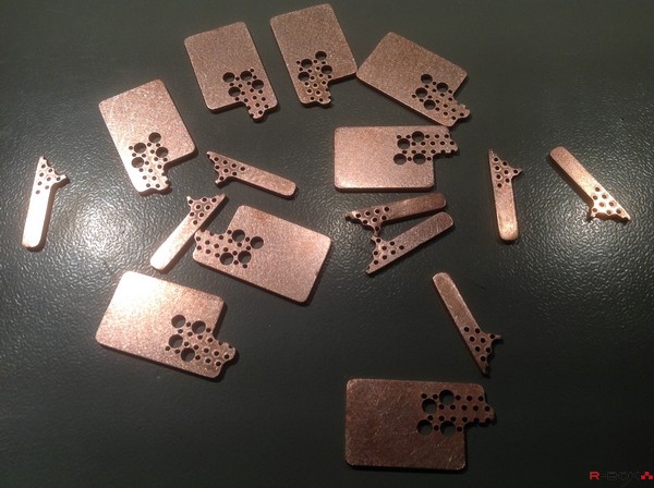
After some brain killing moments Luc and I started desingning 2 pieces of copper that could be soldered directly on the pin’s of the supply and load connector.
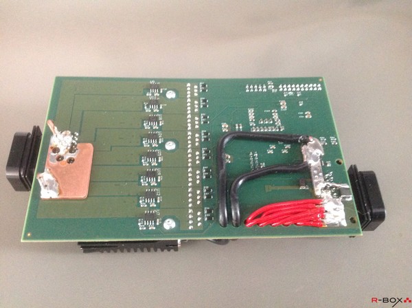
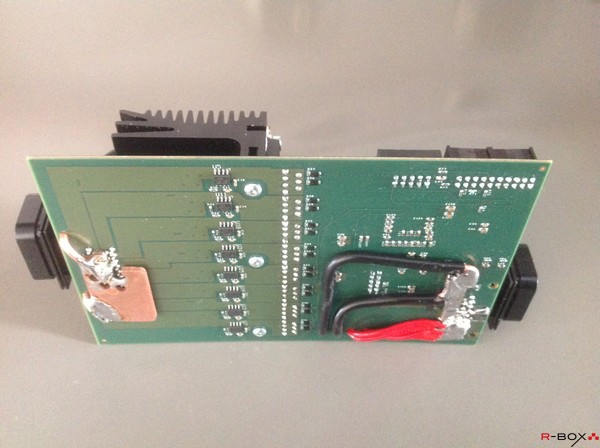
White the great help of Tempac, who cut the copper pieces ultra sharp with the waterjet we now have a solid copper base connected to GND at both sides of the pcb.
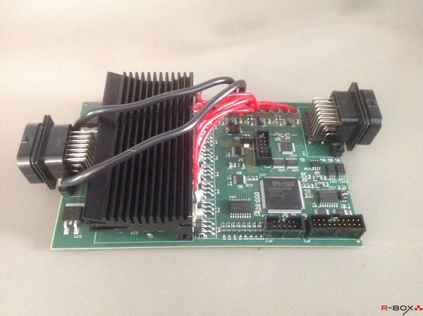
Connecting them together with 2 big wires (6mm2 copper) does the job. We were a bit lucky to find a route from L to R without passing the currents sensors at the bottom of the pcb. The current sensors are hall based sensors so passing currents in the active area would cause distortion of the measurement.
We admit, we will not win any aesthetically prices with this but it is fully functional and accurate now.
It was the only possible fix, otherwis it would have been redo job, which could cost us beside the money another 10-12 weeks delay.
It was an exciting moment but we are extremely that we have found a creative work around.